xMega ADC For Idiots Like Me.
Posted by Tom on Oct 16, 2013
The ADC in Atmel's xMega parts is poorly understood by many, including me. Part of the problem
is the large number of problem versions of the xMega chips where the silly thing just doesn't do
what you think it should. In fact, even in 2013, they often don't do what you think they should.
So I have quite a thread at avrfreaks.net concerning the ADC. I've boiled the results down here
to provide a place to find what I currently know about them. I occasionally edit this page as I learn more.
I currently use the ADC in 2 xMega parts: xMega8E5 and xMega192D3. Some other chips supposedly have
more features and more bugs than these do.
I also haven't tried the event system.
The basic idea.
The basic idea of an ADC is to give you a number that represents the voltage on one of the analog input pins. There is also a dual-ended mode where it will give you a number that represents the difference in voltage on 2 of the analog pins.
So, you use the "Mux" to select which pin you want to measure, which reference voltage to use, and tell it to
go, right? How can this be hard? Well, we're talking xMega here, not ATTiny or ATMega.
My basic code
uint16_t ReadADC(uint8_t Channel, uint8_t ADCMode)
{
if ((ADCA.CTRLA & ADC_ENABLE_bm) == 0)
{
ADCA.CTRLA = ADC_ENABLE_bm ;
ADCA.CTRLB = (1<<4);
ADCA.REFCTRL = 0;
ADCA.EVCTRL = 0 ;
ADCA.PRESCALER = ADC_PRESCALER_DIV32_gc ;
ADCA.CALL = ReadSignatureByte(0x20) ;
ADCA.CALH = ReadSignatureByte(0x21) ;
_delay_us(400);
}
ADCA.CH0.CTRL = ADC_CH_GAIN_1X_gc | ADCMode ;
ADCA.CH0.MUXCTRL = (Channel<<3);
ADCA.CH0.INTCTRL = 0 ;
for(uint8_t Waste = 0; Waste<2; Waste++)
{
ADCA.CH0.CTRL |= ADC_CH_START_bm;
while (ADCA.INTFLAGS==0) ;
ADCA.INTFLAGS = ADCA.INTFLAGS ;
}
return ADCA.CH0RES ;
}
(Thanks to
C Sharp Indepth.com for formatting so you can read it.)
The ReadSignatureByte function.
Of course, to use this code, you'll need the "ReadSignatureByte" function, so here it is.
uint8_t ReadSignatureByte(uint16_t Address)
{
NVM_CMD = NVM_CMD_READ_CALIB_ROW_gc;
uint8_t Result;
Result = pgm_read_byte((uint8_t *)Address);
NVM_CMD = NVM_CMD_NO_OPERATION_gc;
return Result;
}
Using the function
If you know how to include <util/delay.h> you can put this code straight into your program and use it.
The first parameter is the "Mux" pin. Some xMegas have 8 and some 16 analog input pins. The second
parameter, I've labeled "Mode," is usually 1, to measure a pin. If you want to measure one of the internal values, set this to 0. The code uses the 1v reference and "signed" mode, so an input voltage of 0 gives a low result, nearly zero, and a 1v input gives 2047.
"What's this with "nearly zero?'" If you really want to know, google "xMega ADC offset," and try to figure it out yourself. When you understand it, use the Contact option in the menu bar and explain it to me.
Configuring your Input pin
You'll need to configure the input pin, mostly to make sure it's not an output. I make sure the DIR bit on the port is 0, and then I set the PinxConfig to 7 on recommendation of Gabriel at Gabotronics.com
PORTA.DIR = ~(1<<0) ;
PORTA_PIN0CTRL = 7 ;
Out of habit, I set all the pins to output and set them low, unless I want them to be inputs or high. A guy
at an Atmel event said that reduces the power requirements of the chip. You particularly don't want them floating as inputs.
Set up the ADC
I included the init code in the measure function inside an if statement. "If the ADC isn't already
enabled, set it up." You can, of course, move this code to a separate function, especially if you wish to digitize a waveform. Let's look at the key parts of this init code.
Signed Mode? The first surprise is I've selected Signed Mode in the CTRLB register. Why? Well, if you
select Unsigned Mode, a zero input gives you a large positive number. I've heard this explained as a feature so you can measure negative voltages in Unsigned Mode. In my mind this is pretty bogus, if I was expecting a negative number, I'd have used Signed Mode. Anyhow, after much head scratching and unexpected bogus results, one of the freaks at avrfreaks.net suggested I try signed mode, and it gives me much more reasonable results.
Reference Selection I selected the 1v refrence just for ease of calculation. There are other reference voltages available, including external reference voltages. Use the one that makes sense to you. Careful! The xMega has a max on the reference voltage of VCC/1.6 or 0.625 * VCC. I don't know why, go ask your dad.
The Prescaler One place I read said the ADC only works at about 61KHz. This info seems to be bogus. According to app note AVR1300, don't use an ADC clock higher than 2MHz for xMega A devices or higher than 1.4MHz for xMega D devices. According to the xMega32E5 datasheet, between 100KHz and 1.8MHz.
Calibration Bytes Next, I read the 2 calibration bytes out of the processor's signature row.
Sample Control The manual(s) talk about the Sample Control as if it's pretty important, but the register name does not appear in the appropriate IO.h file. Perhaps that means it is critically important. I don't know.
400 MicroSeconds You now have to wait 24 clock cycles or more for the ADC to be ready. I figured 400uS when I thought I had to run the ADC at 61KHz. I think I'm now using 400KHz, so the delay would be more like 70uS, but what the heck, it only takes place once while my program is running.
Channel 0
The xMega manuals wax eloquent on the benefits of multiple channels, but both the D3 and E5 parts have only 1 channel so I have no experience with multipe channels.
ADCA.CH0.CTRL = ADC_CH_GAIN_1X_gc | ADC_CH_INPUTMODE_SINGLEENDED_gc | Mode;
ADCA.CH0.MUXCTRL = (Channel<<3);
ADCA.CH0.INTCTRL = 0 ;
In the channel 0 CTRL register, you set the gain, the input mode and the "Mode" bits to select internal or external measurement. The gain only applies if you're using double ended measurements. Here, I've just used single.
Channel 0's MUXCTRL register selects which pin, or internal signal, you're measuring, so you see I've included the "Channel" parameter from the function call.
I turned off the interrupt 'cause I'm just going to wait for the conversion. You could set it up to "free run," or even do conversions based on some event, and have an interrupt fire whenever a value was ready. You can also sleep the CPU to quiet all the signals while the conversion is running. If you do that, you'll need the interrupt to wake it back up.
Have you gone loopy?
So what's with the loop?
According to Ivar at Atmel, the ADC sample circuit has a MINIMUM rate. According to "Mojo-Chan" at AVR Freaks, the data sheet says 100KHz (thanks). Since I was checking a value every few seconds, I wasn't meeting this specification. He suggested the loop and to take only the second measurement, and it seems fine now.
Actually, now I loop 9 times, summing up the last 8, then divide by 8 by shifting right 3 bits. You don't want to do this if sampling a waveform unless your waveform is pretty slow.
The result
Quoting Atmel without permission:
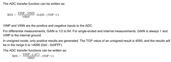
Since I've used signed mode for a single ended measurement, we'll get a value between negative a few and +2047. I'm measuring a voltage that could be as high as 3.6 without destroying the device, so I used a resistor divider to divide by 4, 2047 would be 4v. To display this value, I just multiply the measurement by 40 and divide by 2047, then textually add a decimal point. Yes, I could have used floating point math, but before I was born my mother was frightned by a floating point number and to this day, I still have nightmares of numbers floating in the sky dropping exploding decimal points. Ok, not really.
Calibration
Since I was measuring the battery that runs the device, I wasn't much interested in values near 0 because,
obviously, the device wouldn't be running if the battery was near zero. Since it has a TPS60100 "Charge Pump Regulator," the circuit sees a nice steady 3.3v while the battery is free to drop from 3.6 down to 1.8 or so.
If you are interested in the values close to zero, you'll have to take the offset into account and "Calibrate" your device. Since Atmel has made sure the ADC is nice and linear, all we have to worry about is the offset and the scale.
Offset is the reading you get when you're expecting 0. In my case, it seems to be -30 counts. I found this by shorting the bottom resistor in my 1/4 resistor divider so the pin went to 0 and looking at the count. If you're calibrating your device, you'll want to determine the value with your, or perhaps, each of your devices.
So now, I know to add 30 to each of my measurements to adjust for the offset.
Scale Scale accounts for any errors in gain. With my resistor divider, I just have fractional gain. To determine the scale, set the input to some value near the max you're expecting to read and see what the ADC reads. In my case, it reads about 1/10 of a volt low with an input of 3v. In the olden days, we'd just take out a tiny screwdriver, known as a "tweaker" and adjust the gain of the input amp. Here, since my measurement is 3% off, I just have to adjust the "full scale" number in my equation by 3%.
"So, smarty pants, how do you do THAT with integer math?" Oh, ye of little faith. Remember, I multiplied by 40 and divided by 2047 to get the number to display (x10)? Since I now want to multiply by 4.13, I just multiplied by 413 and divided by 20470.
In production, I'd just order 1% resistors instead of the 5% resistors I have in place, and not worry about it.
Now, you know how to calibrate your reading. You would be surprised how often you don't need to worry about it. Suppose I was digitizing a sound to transmit or store, and reproduce: In that case, it just doesn't matter if there's a 30 count offset or a 3% inaccuracy.
Accuracy and Repeatibility
Often, your ADC will give you wildly varying readings. These are caused by noise on your AVCC and on your reference. The biggest improvement I've found is to place an inductor between the AVCC and VCC nets, and put a 1uF capacitor on the AVCC pin itself.
Info from Atmel
•AVR1012 xMega A Schematic Checklist.
•AVR1300 Using the xMega ADC.