
The NRF24L01+ and the AVR xMega processor
Posted by Tom on Jan 14, 2014
There are dozens of pages on the web showing how to use the NRF24L01+. Just google! So why do we need another? Perhaps because I'm a childish brat who wants to say, "Me too! Me too!"
Counterfeit NRF24L01+ are so readily available, so cheap and so easy to use, that it just seems silly to use wires, or even strings, to communicate data between devices. You can find them for a dollar or two on ebay, and for less than 10 dollars, you can find them with amplifiers and antennas that extend the range dramatically. Even with just the PC trace antennae, I've made them work 2 or 3 hundred feet away. Of course, I also paid $10 for a pair from dx.com that have stubby antennae and seem to work half as far as the 1 dollar variety. Go figure.
There is an older chip from Nordic Semiconductor called the NRF24L01. Here, I'm talking specifically about the NRF24L01+ part. I don't think you'll even find the older ones anywhere.
Beware of cheap imitations. I've never actually seen one of these, but if I don't say this, somebody will say I'm not warning you. If I have seen a cheap imitation, it must work pretty well 'cause I don't know it. And indeed, I have! ALL my modules are counterfeit. They might actually be SI24R1 parts fraudulently labled NRF24L01+. See Hackaday NRF24L01+ Real vs Fake
Beware also of Mouser? Now, Mouser is one of my reliable sources, and on small quantities like I buy, they often beat Digikey on price. I have no idea why Mouser thinks NRF24L01+ modules are $40+! Don't believe me? Just search!
xMega
If you're used to AVR tiny and mega processors, the xMega might be a bit of a shock. I know it was to me. Except for the numerous errata, they do work mostly as described in the PDFs. Realize, though, that there are 2 PDFs. One contains all the programming info for the "family" of xMega parts, and one the specifics for the part you have in your hand, but only sketchy programming information. Why? I do not know, go ask your dad.
With many examples on the web for ATTiny and ATMega, I'll show code for the xMega.
Style A
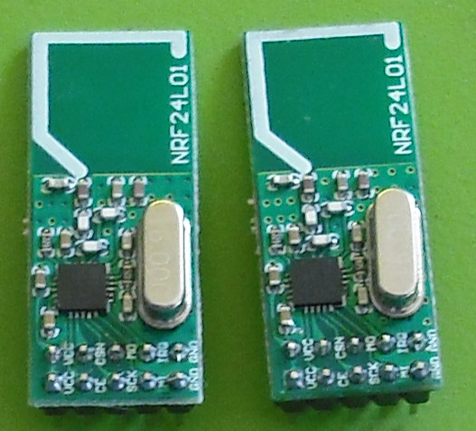
This is the first style I bought, and I paid about 2 bucks each for 10 of them several years ago. Outdoors, these reach about 200 ft. I could set one on my workbench and go out my apartment door, down the stairs, out the front door of the building and a good ways down the driveway.
Style B
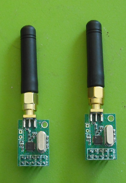
These came from dx.com for about 10 bucks. I figured as well as the plain ones work that these should go a long ways! They were a grave disappointment. They reach about 1/2 as far as Style A. There was a long discussion at avrfreaks.net as to why this might be. Some thought they'd work well mounted in a metal box with just the antennae peeking out. I haven't tried that.
Style C
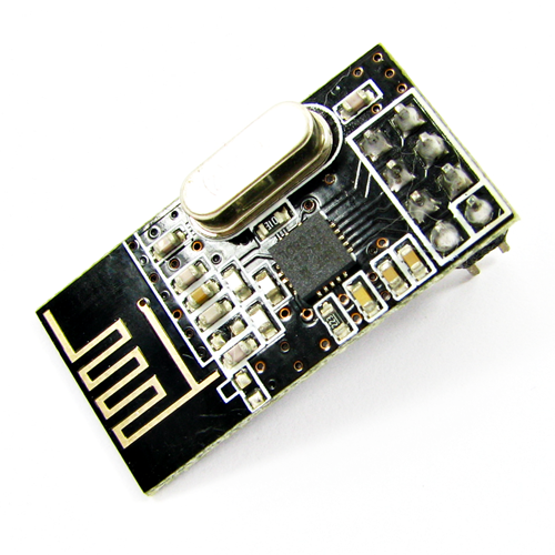
This style has only 8 pins, providing just 1 for +3 and ground. I haven't had a chance to compare their range to Style A, but they seem to work very nicely. They are physically smaller. Nordic Semiconductor shows layouts for both Style A and Style C in their data sheets.
I took a train controlled by a remote and receiver I built with a pair of these to a big train show. I expected a madcap comedy along the lines of keystone cops as I chased a runaway train, or couldn't get it to go, but the silly thing behaved flawlessly all weekend. At one point, somebody asked about the range. "I don't know, it works as far as I've ever tried it." So I started walking away and counting steps. The remote display showed if it get an ack from a packet, and I found a place where I could step forward one step and have contact, back one step and loose contact. I was 300 ft away. I didn't expect it to work that far. This was in a pretty noisy environment with toy trains everywhere and lots of 2.4GHz devices.
Style D
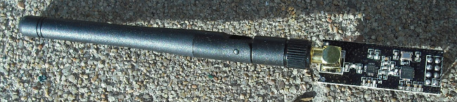
I got this for $6 from ebay. I have an application where Style B modules almost work, so I'm hoping this and a Style B will work at low speed.
Should have got 2 and experimented with them, but budget was horribly limited at the time.
Wiring it up
The NRF24L01+ chip has 6 connections to your processor:
- SI - Serial in. Goes to your MOSI.
- SO - Serial Out. Goes to your MISO.
- SC - Serial Clock. Goes to your SCK.
- CS - Chip Select. Put it low to talk to the NRF.
- CE - Chip Enable. Out it to a port pin 'cause you'll need to drive it high and low.
- INT - Optionally connect this to an interrupt pin so the NRF can tell you when a message has arrived or has been sent.
It's a 3v part
The NRF is a 3v part. While its processor connections can be connected to a 5v system, it needs 3v, not 5 on it's + input.
Cure for the common code
So, here's how I organize my programs: Poorly? I keep a library of .h and .c files in a library folder and include them as "links" in any programs I wish to use them. Any specifics about the project are specified in Config.h. So all the .c files in the library folder include Config.h so they know the specifics of the project. If you want to use library folders this way, see this thread at AVRFreaks.net where CLAWSON instructed me. Otherwise, just put the info in your project and be done with it. What? Don't you use the word "betwixt" in everyday conversation?
SPI in the XMega
spi.h
#ifndef SPI_H_
#define SPI_H_
#include <avr/io.h>
void spiopen(void);
uint8_t spi(uint8_t val);
void spiclose(void);
#endif
My SPI code provides 3 functions:
- void spiopen(void) This prepairs the SPI gizmo for use.
- void spiclose(void) This unprepairs the SPI gizmo for use and puts the direction of the port pins back the way they were. You may not need this, but like a knucklehead, I used the top of PortC for another function as well.
- uint8_t spi(uint8_t val) This sends a byte out to the spi device and returns the byte that came from the spi device. SPI is full duplex, as you shift bits out, bits shift in.
spi.c
#include "spi.h"
#include "Config.h"
uint8_t SPIDir = 0 ;
void spiopen(void)
{
SPIDir = SPIPort.DIR ;
SPIPort.DIRCLR = (1<<SPIMI);
SPIPort.DIRSET = (1<<SPIMO) | (1<<SPISC) | (1<<SPISS) ;
SPIC.CTRL = SPI_ENABLE_bm | SPI_MASTER_bm | SPI_MODE_0_gc | SPI_PRESCALER_DIV64_gc;
}
void spiclose(void)
{
SPIC.CTRL = 0;
SPIPort.DIR = SPIDir ;
}
uint8_t spi(uint8_t val)
{
SPIC.DATA = val ;
while(!(SPIC.STATUS & (1<<7)));
return SPIC.DATA;
}
Notice that the .c file includes the Config.h file. Because I always forget, there's a comment there to tell me what it expects to find in the Config.h. You see that on this project, SPI is the top 4 bits of PORT C. Some XMega parts seem to have it on the lower bits of PORT C.
Now, you see that I make use of a feature of the XMega devices, or maybe just of the io.h for them. I don't know, but it works handily. I can specify an equate for one of the ports, then refer to all the registers of that port, since they are just items in a struct.
So, I save the direction control of port C into a local variable so that spiclose can put it back the way it was. Then I set the SPIMI pin to an input, the SPIMO, SPISC and SPISS pins to outputs. Important to set the slave select pin to output or the spi gadget will confuse you because it's trying to be the spi slave, not the spi master. I then set up the SPI.CTRL register. For want of a good reason, I always use SPI_PRESCALER_DIV_64. I probably should make that a parameter, but it seems to work this way in 32MHz systems as well as 2MHz systems, so I don't worry about it.
SPIclose just undoes what spiopen did.
The spi function does the work. You see that in XMega, it's very simple. It puts the byte to SPIC.DATA, waits for bit 7 in the SPIC.STATUS register to go high, then fetches SPIC.DATA to return to the caller.
There you have the basics of spi in an XMega. True, the article is about NRF, but we had to get spi working first.
The code we've all been waiting for
nordic.h
#ifndef NORDIC_H_
#define NORDIC_H_
#include <avr/io.h>
uint8_t NRFLastSent[6];
uint8_t NRFReadRegister(uint8_t reg);
uint8_t NRFWriteRegister(uint8_t reg, uint8_t value);
void NRFInit(uint8_t pSpeed);
#define NRFslow 0b00100110
#define NRFfast 0b00001110
#define NRFhalffast 0b00000110
void NRFSetRxAddress(const __memx uint8_t * Bytes5);
void NRFSetChannel(uint8_t Ch) ;
#define dNRFModePD 0 ;
#define dNRFModeRX 3 ;
#define dNRFModeTX 2 ;
uint8_t NRFGetMode(void) ;
void NRFModePowerDown(void);
void NRFModeTX(void);
void NRFModeRX(void);
uint8_t NRFIsModePowerDown(void);
uint8_t NRFIsModeTX(void);
uint8_t NRFIsModeRx(void);
uint8_t NRFSendPacket(const __memx uint8_t *ToAddress, uint8_t *Packet, uint8_t Length);
void NRFSendPacketNoAck(const __memx uint8_t *ToAddress, uint8_t *Packet, uint8_t Length);
uint8_t NRFReceivePacket( uint8_t * Packet);
uint8_t GetPW(void);
#endif
nordic.c
#include "Nordic.h"
#include "Config.h"
#include "spi.h"
#include <avr/io.h>
#include <string.h>
#include <util/delay.h>
#define CMD_READ_REG 0x00
#define CMD_WRITE_REG 0x20
#define CMD_RD_RX_PLOAD 0x61
#define CMD_WR_TX_PLOAD 0xA0
#define CMD_FLUSH_TX 0xE1
#define CMD_FLUSH_RX 0xE2
#define CMD_REUSE_TX_PL 0xE3
#define CMD_R_RX_PL_WID 0x60
#define CMD_W_ACK_PAYLOAD 0xA8
#define CMD_W_TX_PLOADD_NK 0xB0
#define CMD_NOP 0xFF
#define RG_CONFIG 0x00
#define RG_EN_AA 0x01
#define RG_EN_RXADDR 0x02
#define RG_SETUP_AW 0x03
#define RG_SETUP_RETR 0x04
#define RG_RF_CH 0x05
#define RG_RF_SETUP 0x06
#define RG_STATUS 0x07
#define RG_OBSERVE_TX 0x08
#define RG_CD 0x09
#define RG_RX_ADDR_P0 0x0A
#define RG_RX_ADDR_P1 0x0B
#define RG_RX_ADDR_P2 0x0C
#define RG_RX_ADDR_P3 0x0D
#define RG_RX_ADDR_P4 0x0E
#define RG_RX_ADDR_P5 0x0F
#define RG_TX_ADDR 0x10
#define RG_RX_PW_P0 0x11
#define RG_RX_PW_P1 0x12
#define RG_RX_PW_P2 0x13
#define RG_RX_PW_P3 0x14
#define RG_RX_PW_P4 0x15
#define RG_RX_PW_P5 0x16
#define RG_FIFO_STATUS 0x17
#define RG_DYNPD 0x1C
#define RG_FEATURE 0x1D
#define MASK_RX_P_NO 0x0E
#define MASK_IRQ_FLAGS 0x70
#define MASK_RX_DR_FLAG 0x40
#define MASK_TX_DS_FLAG 0x20
#define MASK_MAX_RT_FLAG 0x10
#define MASK_RX_FIFO_EMPTY 0x01
#define ModeBits 0b00111100
#define CSHIGH RFcsPORT.OUTSET = (1<<RFcsn)
#define CSLOW RFcsPORT.OUTCLR = (1<<RFcsn)
#define CEHIGH RFcePORT.OUTSET = (1<<RFce)
#define CELOW RFcePORT.OUTCLR = (1<<RFce)
static __inline__ uint8_t CS(uint8_t hl)
{
if (hl==1)
{
spiopen();
CSLOW;
}
else
{
CSHIGH;
spiclose();
}
return hl;
}
#define CHIPSELECT for (uint8_t cs = CS(1); cs==1; cs = CS(0))
uint8_t WriteBuffer(uint8_t reg, const __memx uint8_t *pBuf, uint8_t bytes);
uint8_t ReadBuffer(uint8_t reg, uint8_t *pBuf, uint8_t bytes);
void NRFSetTxAddress( const __memx uint8_t * SendTo);
uint8_t NRFIsRxPacket(void);
uint8_t NRFWriteRegister(uint8_t reg, uint8_t value)
{
uint8_t status;
CHIPSELECT
{
status = spi(CMD_WRITE_REG+reg);
spi(value);
}
return(status);
}
uint8_t NRFReadRegister(uint8_t reg)
{
uint8_t reg_val;
CHIPSELECT
{
spi(CMD_READ_REG+reg);
reg_val = spi(0);
}
return(reg_val);
}
uint8_t WriteBuffer(uint8_t reg, const __memx uint8_t *pBuf, uint8_t bytes)
{
uint8_t status, i;
CHIPSELECT
{
status = spi(CMD_WRITE_REG+reg);
for(i = 0; i < bytes; i++)
{
spi(*pBuf++);
}
}
return(status);
}
uint8_t ReadBuffer(uint8_t reg, uint8_t *pBuf, uint8_t bytes)
{
uint8_t status,
i;
CHIPSELECT
{
status = spi(CMD_READ_REG+reg);
for(i = 0; i < bytes; i++) {
pBuf[i] = spi(0);
}
}
return(status);
}
void NRFSetRxAddress(const __memx uint8_t * Bytes5)
{
WriteBuffer(RG_RX_ADDR_P0, Bytes5, 5);
WriteBuffer(RG_RX_ADDR_P1, Bytes5, 5);
}
void NRFSetTxAddress(const __memx uint8_t * SendTo)
{
WriteBuffer(RG_TX_ADDR, SendTo,5);
WriteBuffer(RG_RX_ADDR_P0,SendTo,5);
for (uint8_t i = 0; i<5; i++) NRFLastSent[i] = SendTo[i];
NRFLastSent[5] = 0;
}
uint8_t NRFGetMode(void)
{
return NRFReadRegister(RG_CONFIG)&2 ;
}
void NRFModePowerDown(void)
{
CELOW;
NRFWriteRegister(RG_CONFIG,ModeBits) ;
}
void NRFModeTX(void)
{
CELOW;
uint8_t m = NRFReadRegister(RG_CONFIG);
NRFWriteRegister(RG_CONFIG,ModeBits|2) ;
if ((m&2)==0) _delay_ms(5);
}
void NRFModeRX(void)
{
NRFWriteRegister(RG_CONFIG,ModeBits|3);
CEHIGH;
}
uint8_t NRFIsModePowerDown(void)
{
uint8_t ret = 0 ;
if ((NRFReadRegister(RG_CONFIG)&2)==0) ret = 1;
return ret;
}
uint8_t NRFIsModeTX(void)
{
uint8_t m = NRFReadRegister(RG_CONFIG);
if ((m&2)==0) return 0;
if ((m&1)==0) return 1;
return 0;
}
uint8_t NRFIsModeRx(void)
{
uint8_t m = NRFReadRegister(RG_CONFIG);
if ((m&2)==0) return 0;
if ((m&1)==0) return 0;
return 1;
}
void NRFSetChannel(uint8_t Ch)
{
NRFWriteRegister(RG_RF_CH, Ch);
}
volatile uint8_t pw = 0;
uint8_t GetPW(void)
{
return pw ;
}
uint8_t NRFReceivePacket( uint8_t * Packet)
{
if ((NRFReadRegister(RG_STATUS)&(1<<6))==0) return 0;
CELOW ;
CHIPSELECT
{
spi(CMD_R_RX_PL_WID);
pw = spi(0);
}
if (pw>32)
{
CHIPSELECT
{
spi(CMD_FLUSH_RX);
}
NRFWriteRegister(RG_STATUS,(1<<6)) ;
return 0;
}
CHIPSELECT
{
spi(CMD_RD_RX_PLOAD);
for(uint8_t i = 0; i<32; i++) Packet[i] = spi(0);
}
NRFWriteRegister(RG_STATUS,(1<<6)) ;
CEHIGH ;
return 1;
}
uint8_t NRFIsRxPacket(void)
{
uint8_t ret = NRFReadRegister(RG_STATUS) & (1<<6) ;
return ret ;
}
void NRFSendPacketNoAck(const __memx uint8_t *ToAddress, uint8_t *Packet, uint8_t Length)
{
uint8_t ModeIs = NRFReadRegister(RG_CONFIG);
NRFModeTX();
NRFSetTxAddress(ToAddress);
NRFWriteRegister(RG_EN_AA,0);
CHIPSELECT { spi(CMD_FLUSH_TX); };
CHIPSELECT
{
spi(CMD_WR_TX_PLOAD);
for (uint8_t i = 0; i<Length; i++) spi(Packet[i]);
};
CEHIGH;
_delay_us(11) ;
CELOW;
if ((ModeIs & (1<<1)) == 0) NRFModePowerDown() ;
if ((ModeIs & 3) == 3) NRFModeRX();
}
uint8_t NRFSendPacket(const __memx uint8_t * ToAddress, uint8_t *Packet, uint8_t Length)
{
uint8_t ModeIs = NRFReadRegister(RG_CONFIG);
CELOW;
NRFModeTX();
NRFWriteRegister(RG_EN_AA,3);
NRFSetTxAddress(ToAddress);
CHIPSELECT
{
spi(CMD_FLUSH_TX);
};
CHIPSELECT
{
spi(CMD_WR_TX_PLOAD);
for (uint8_t i = 0; i<Length; i++) spi(Packet[i]);
};
CEHIGH;
_delay_us(15) ;
CELOW;
uint8_t st = 0;
while ((st & ((1<<5) | (1<<4)))==0) st = NRFReadRegister(RG_STATUS);
NRFWriteRegister(RG_STATUS,st & ((1<<5) | (1<<4)));
if ((ModeIs & (1<<1)) == 0) NRFModePowerDown() ;
if ((ModeIs & 3) == 3) NRFModeRX();
return (st>>5) & 1;
}
typedef struct
{
uint8_t r ;
uint8_t v ;
} initline ;
void NRFInit(uint8_t pSpeed)
{
CSHIGH;
CELOW;
_delay_ms(200);
NRFWriteRegister(RG_CONFIG,ModeBits);
NRFWriteRegister(RG_EN_AA,3);
NRFWriteRegister(RG_EN_RXADDR,3);
NRFWriteRegister(RG_SETUP_AW,3);
NRFWriteRegister(RG_SETUP_RETR,0x18);
NRFWriteRegister(RG_RF_CH,2);
NRFWriteRegister(RG_RF_SETUP,pSpeed);
NRFWriteRegister(RG_DYNPD,3);
NRFWriteRegister(RG_FEATURE,0b100);
NRFWriteRegister(RG_RX_PW_P0,32);
NRFWriteRegister(RG_RX_PW_P1,32);
}
What do we do with all this?
NRFReadRegister and NRFWriteRegister I exposed these so you can maniuplate the NRF yourself. There are lots of features I'm not using, that you might want.
void NRFInit(uint8_t pSpeed) Before you can do anything with it, you must use NRFInit. This takes a parameter to select which speed, 2000000bps, 1000000bps or 250000bps. There are 3 defines:
- #define NRFslow 0b00100110 -- NRFInit(NRFslow)
- #define NRFfast 0b00001110 -- NRFInit(NRFfast)
- #define NRFhalffast 0b00000110 -- NRFInit(NRFhalffast)
You might wonder why you'd ever want to use a low speed. I can think of 2 reason, either because you're communicating with another device that already runs slow, or you need more range. The receiver sensitivity increses several db at lower speeds. If, at NRFfast, you don't have quite enough range, try NRFslow, but don't forget to change both ends, or you won't get anything through.
There is a _delay_ms(200) call, so your Config.h needs to define F_CPU. The whole reason for this delay is to be sure you don't try to talk to the NRF before it's ready. If you're sure you won't try to init it for 200ms, you can skip this delay.
void NRFSetRxAddress(const __memx uint8_t * Bytes5) I use 5 byte addresses. You can use different address lengths if you like, you'll need to change the NRFInit function.
void NRFSetChannel(uint8_t Ch)This sets the channel, 0 through 255. Note that in USA, only 0-83 are legal for ISM band use. You might get away with it, but I'm not that lucky. Remember, if you're running 2Mbps, you're using 2MHz bandwidth and will interfere with one on an adjacent channel. In most cases, you won't even have to think about this, but don't say I didn't tell you. I've never tried receiving a message an an adjacent channel, so I have no idea if it will work.
The Modes The NRF has 3 modes, Power Down, Transmit and Receive. In Transmit and Receive mode, the part uses like 13mA of power. Since it only transmits 1mW, there wasn't enough difference between tx current and rx current for me to worry about. 6 functions set and test the modes:
- void NRFModePowerDown(void);
- void NRFModeTX(void);
- void NRFModeRX(void);
- uint8_t NRFIsModePowerDown(void);
- uint8_t NRFIsModeTX(void);
- uint8_t NRFIsModeRx(void);
uint8_t NRFSendPacket(const __memx uint8_t *ToAddress, uint8_t *Packet, uint8_t Length) This is the main send packet method. It transmits a packet pointed to by *Packet and waits for an ack, returning 0 if there was no ack. There's something funny about NRFs: The packet doesn't contain a "from" address so the reciever sends the ack to its own receive address. To receive the ack, the sender had to set its receive address to the address it was transmitting to. If you're expecting to go back to receive mode, you'll need to set the receive address after sending the packet.
I init the module for "Dynamic Packet Length," so the receiver doesn't reject packets of different lengths.
__memx Notice that I used __memx for the address. This lets you pass a pointer in flash, ram or even eeprom. Setting NVM_CTRLB |= (1<<3) lets you read (but not write) the eeprom as if it was ram. I just used a plain pointer for the packet itself figuring you'd probably not be sending data out of flash.
void NRFSendPacketNoAck(const __memx uint8_t *ToAddress, uint8_t *Packet, uint8_t Length) This sends a packet without asking for or waiting for an ack from the receiver.
uint8_t NRFReceivePacket( uint8_t * Packet) This checks for a packet in the receive buffer. If there is none, it returns a zero. Otherwise, it stuffs the packet into the memory pointer. It's up to you to be sure the packet will fit. NRF packets are never bigger than 32 bytes.
Examples
To initialize the module NRFInit(NRFFast) -- This puts the module in power down mode so it's not drawing much current.
To set the channel NRFSetChannel(6) The number may be 0 through 255, except in US, only numbers less than 84 are allowed.
To send a packet First, assemble your packet in memory, and call NRFSendPacket. SendPacket can find the send-to address in ram, flash, or even eeprom.
- NRFSendPacketNoAck(PSTR("ABCDE"), &Packet, 8) -- This will send an 8 byte packet to a fixed address.
- NRFSendPacketNoAck(&SomeVar, &Packet,16) -- This sends a 16 byte packet to an address stored in a 5 byte area in memory.
- NRFSendPacket(PSTR("EDCBA"), &Packet, 24) -- Returns non zero if it got a response from the receiver.
- NRFSendPacket(&SomeVar,&Packet,32) -- Returns non zero if it got a response from the receiver.
These functions set the module to TX mode, then return it to the
Tips
There are a couple things about the NRF that can confuse you. Or at least, they confused me.
1 The receiver can miss packets if you send the same data again. The receiver sends an ack packet to the sender when it receives a packet. Of course, this ack may itself get lost. If the transmitter doesn't see the ack within a specific time, it sends the packet again, so it is possible to receive the same packet twice or more times. The Nordic prevents this by watching for the same packet to come again, and ack's the repeat packet, but doesn't notify your gadget. There are 2 bits of packet identifier in the header so the receiver can tell if this is a retransmitted packet. Except, this doesn't always work. I find if you're sending the same packet repetedly, the receiver often will receive the first, and throw the rest away. To correct this, I reserve one byte of the 32 byte (or less) packet for a "packet number" and increment it on every transmit so I don't actually send the same data over.This seems to be a symptom of the counterfeit parts and doesn't happen with real Nordic parts.
2 Sending a packet sets the nordic's receive address to the address it sent the packet to. You see, the packet doesn't contain a source address, so to ack the packet, the receiver sends an ack to the same address it just received the packet. So to receive the ack, the transmitter had to change the receive address to the address it sent the packet to. So if you intend to listen on one address and send messages to other addresses, don't forget to set the receive address back after sending a packet.
About the counterfeit parts.
It seem there are 3 complaints about the counterfeit parts. 1. They use a little more power than real NORDIC parts. 2. The receiver has a little less sensitivity. 3. The transmitter might be a little more powerful. And E, the frequency might not be as well controled near the ends of the band.